


Primer of Marine Propulsion Part 5
Primer of Marine Propulsion Part 5
Gas turbines...


I had intended this portion of the series be different than the others but once again, my ambition was larger than my mental bandwidth and this thing started to turn into a book instead of an essay. Most of my knowledge comes from studying marine propulsion ever since I was able to understand what made ships move through the water and from being a huge nerd through my own study of equipment manuals, engineering books, and maritime history as well as from formal and informal training while in the US Navy. My experience comes from 20 years of working in the field of marine engineering. I do have operational experience with regards to gas turbine electrical power generation systems and propulsion systems but I have no maintenance and repair experience and no formal training other than on the job training.
I was never really interested in gas turbine propulsion until I was assigned to the USS Ticonderoga. However, after seeing the machinery in operation and learning how it did what it did, I became incredibly interested and learned what I could in the short time that I had on that vessel. My function on the vessel was not in the Main Propulsion division but rather in the Auxiliary division where we were responsible for every friggin engineering thing that was outside of Main Propulsion. Due to this, my time to learn these engines was considerably limited but I have always remained curious about them.
Most of what I have written in this series has come from my own knowledge and experience along with doing a little research. In order to write this part, I had to get into some books and do some digging on the interwebz in order to fill in the missing pieces. What I found is that there is much more to the story of these engines than what I could’ve imagined, which I guess is typical of pretty much everything once we actually try to learn something about something.
What I hope to accomplish here with this entire series, and in everything else that I write and share, is to produce something that will expand the readers horizons so to speak as well as to spark something in the younger generation that may lead them into the trades and engineering. I want to help drive curiosity on the part of the reader. That takes time and development of my own abilities and hopefully this is a step in that direction for me.
You be the judge and tell me if I’ve accomplished what I set out to accomplish here and as always, feel free to ask questions or leave comments below. Questions help us both learn and comments draw the conversations together.
Introduction
Gas turbine engines are kind of the new kid on the block in the marine propulsion world. They showed up in the 1950’s and became one of the most widely used forms of propulsion used by navies through out the world and their use is slowly growing in the commercial maritime industry.
In service, these engines have multiple applications in the marine world. They’re used for propulsion engines, electric power generators, co-generation, and as the prime mover for natural gas compressors on offshore oil/gas production platforms. In the co-generation application, the engine is used to power an electrical generator and the exhaust gases are used to turn water in to steam which can be used for providing hot water for plant services and by the folks that are riding that particular vessel or the steam can be used to power steam turbines for plant use, propulsion, or electrical generators.
Since it’ s been a while since I wrote the other parts, it may be helpful to review the other parts of this series. This one is more technical than the others and kinda builds on the previous sections. I’ve linked them below:
Part 1 The introduction
Part 2 Steam Powah!
Part 3 Diesel Powah!
Part 4 Big Diesel Powah!
History
The first recorded idea for a gas turbine was Patented back in 1797 by a Mr. John Barber of the UK. The machine that he patented was never built. In 1904, a German fella by the name of Franz Stolz built the first gas turbine but its operation was considered unsuccessful, though it was a step in the right direction and spurred further development by others. In 1910, another German dude, managed to get one to run on some level but it wasn’t considered a success either.
Development would follow two separate paths, the aeronautical path and the industrial path, both of which would impact the development of turbines in the marine world. In 1939 the first successful gas turbine powered power plant (industrial engine) was in operation in Switzerland and the first successful turbine powered jet aircraft, a Heinkel He-178, took to the skies. Germany, Britain, and the US continued to develop jet powered aircraft throughout the 1940s, with the Germans flying the ME-262 in 1942 and deploying the aircraft in 1944. The Limeys followed closely with the Gloster Meteor in 1944 and the Yanks with the P-80 Shooting Star in 1945.


The first Naval use of gas turbines was by the British in 1947 with the conversion of , closely followed by the US Navy, though the applications were different. The Royal navy’s first use of gas turbines was for propulsion while the US Navy’s use was a generator in minesweepers.
Interestingly enough, after World War 2, there was some gubmental interest in commercial gas turbine powered vessels and several liberty ships were converted to test beds. The ships were operated as commercial vessels by various marine transportation companies but the conversions were funded by the US Maritime Administration (MARAD).
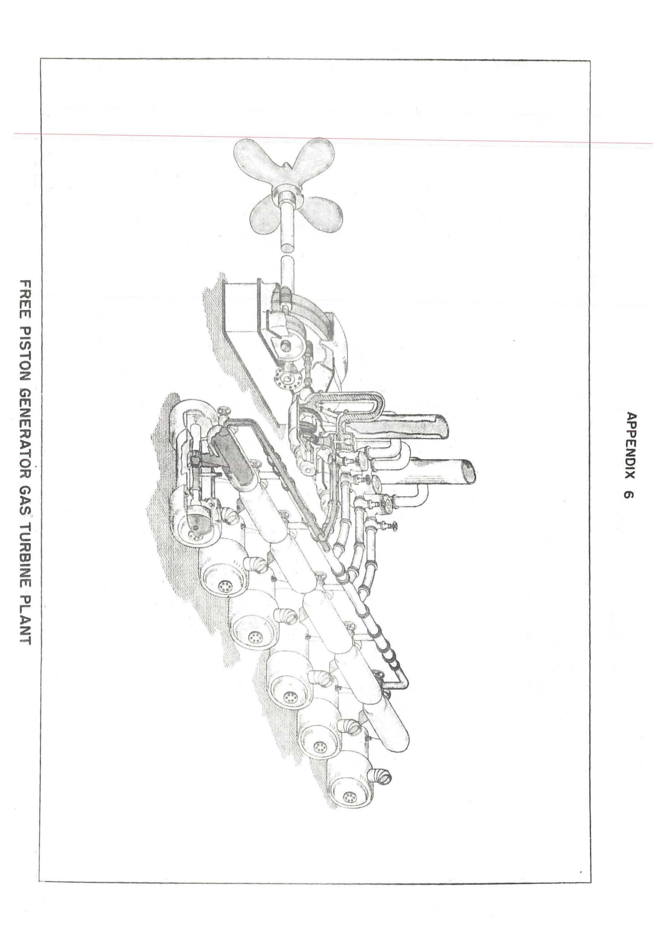
There were two main variations of gas turbine systems installed for the tests; one that was essentially a conventional gas turbine system with early controllable pitch propeller and the second variation used something known as a free piston gas generator that powered two individual turbines, one for ahead and one for astern operation. I’m not going to talk about this second variation as it was only used for the tests… plus these are some odd and unique systems that could really have their own essay in order to explain how they worked. The first version is an early version of what we are discussing in this essay.
Overall, the tests were considered successful after both ships put several years worth of operations astern. Ultimately, in business if it doesn’t make dollars then it doesn’t make sense so the ships were converted back to steam power and operated as such.
As time has gone by, commercial gas turbines are finding use in offshore oil installations, high speed ferries, and cruise ships. In the future, these engines will be found on LNG tankers, more cruise ships, and possibly other cargo ships. Because there is little use difference between the gas turbines used in the electrical power generation industry, aviation, and in naval service, technological innovation has continued and increased to where gas turbines may very well find more use in the maritime industry.
Plant Operation and Use
When in operation, these engines remind me a lot of the typical modern male college graduate; they require a high degree of technology and close supervision in order to operate properly and for any length of time, the engines must be kept clean, they tend to work when they want to and the harder they work the more they whine. But they are also capable of producing a tremendous amount of work and being incredibly efficient when used in the proper application.
As used in propulsion service, these engines essentially function the same as the medium speed diesel engines. Two turbines are usually connected to a common reduction gear which turns a propeller shaft. This configuration is often referred to a COGAG plant, which means COmbined Gas turbine And Gas turbine. The turbines can be clutched in and out as needed. Typically, one turbine per shaft is used but when there is a need for high speed operations, both turbines are operated together. For the most part, this type of system uses a controllable pitch propeller for propulsion since these engines don’t reverse and are most efficient at constant speeds.
Other than a few pieces of equipment necessary for the operation of the turbines, the engine room of a gas turbine powered ship would look very similar to the engine room of a diesel powered ship. Really, the only differences in appearance would be the large enclosure that contain the engines, a larger reduction gear, and a separate oil cooler and reservoir for the turbine oil.
Gas turbines are primarily used by naval vessels because they can create high amounts of power in a compact unit that is lightweight for the amount of power that they are capable of generating. For example, the General Electric LM-2500 series of engines are capable of generating between 20,000 HP and 30,000 HP depending on the configuration. Gas turbines when used in the commercial maritime role are usually used as generators on cruise ships and may find use as generators on LNG tankers since these engines work really well when burning natural gas as a fuel and LNG tankers are constantly off gassing natural gas.
Just as a note, most of what I am writing about here relates to General Electric LM 2500 series as they are most common through out the world.
How They Work
I probably should’ve added this section to the steam propulsion portion of the series but I didn’t think to at the time. My bad…
A turbine is a machine that converts thermal (heat) energy into mechanical energy which is then used to produce power (power being defined as work accomplished over time). For this discussion, the heat comes from burning a hydrocarbon based fuel. When a fuel is burned, chemical energy is converted into thermal energy through the oxidizing of a carbon based substance. The heat energy that is produced during the combustion process produces a gas, which under ideal conditions would only be carbon dioxide and water vapor, and it is this gas that carries the heat of combustion. When a substance is heated, it expands and if that heated gas is contained, then it will increase pressure within the vessel in which it is contained. Pressure is a force, which will be important in a moment. This gas also has the property of weight, which is also important because this gives the gas mass which is what is needed in order to make the magic happen.

So basically… a fuel is burned to produce a high temperature gas. This part of the process happens inside of the combustors or burners. The combustor is simply an individual can shaped component or an annular area that has a constrictive opening on the outlet side, which acts as a nozzle. This gas tries to expand but is partially constrained inside the combustor and released through the nozzle. Because the gas is generated faster than it can be released through the combustor nozzle, it builds pressure. This controlled release of high temperature gas produces a high velocity flow of the gas. High velocity combined with the mass of the gas gives us force. The more force we have, the more power generated. Once the engine is started and reaches a self sustaining speed, the combustion process is continuous. Initially, fuel ignition is started using electric ignitors, similar to spark plugs in a car engine. Ignitors are used to initiate combustion but are turned off once the engine is able to run itself.
Engine Components and Systems Operation
Module and Enclosure
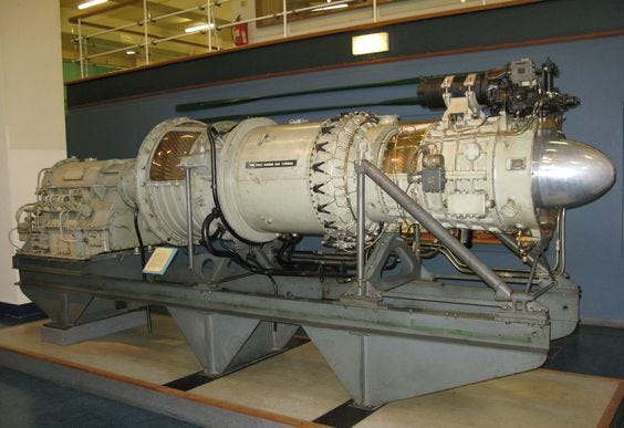
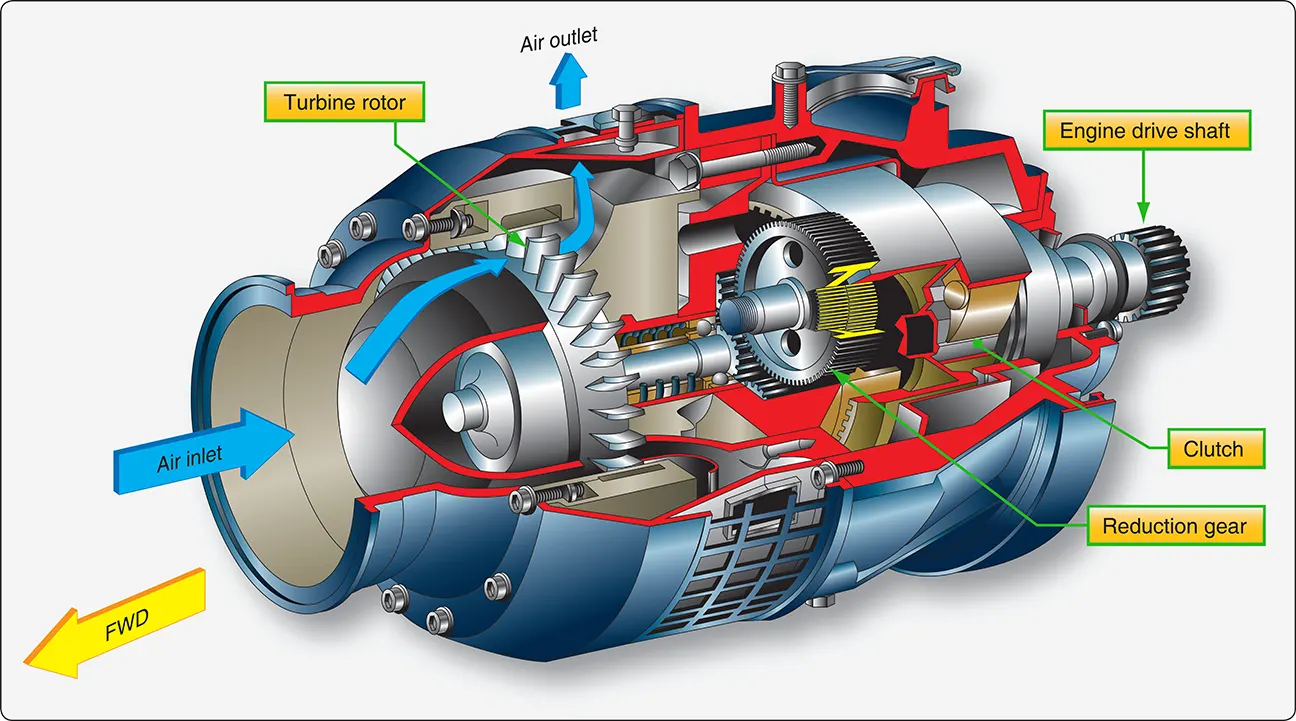
The engines themselves are usually contained inside of a container, called a module, which is roughly the size of a CONEX box. These modules help to isolate the considerable high pitch noise, contain fire fighting agents in the event of a fire, and to help isolate the heat from the engine radiating out into the engineering spaces.


 Gas Turbine.jpg")
Mechanical Operation
Mechanically speaking, these engines are incredibly simple. In a simple turbine, there is really only one main part that is responsible for making power. Even the more complex turbines are more simple than a reciprocating engine but turbines require some advanced materials and manufacturing techniques in order to operate efficiently and for long periods of time. These engines are the epitome of precision in manufacturing, engineering, and materials science.
The engines draw atmospheric air in through the inlet at the front of the engine and compress that air through a series of compressor blades. These blades are arranged in stages so that as the air is compressed, it passes through a set of guide vanes and then to the next stage of compression. The compressed air is then passed to the combustor section where it is mixed with fuel and burned. This produces the high velocity gas that is used to make the turbine section work. The gas pushes on the turbine blades forces and forces the blades to rotate on a shaft, which also turns the compressor blades. When the turbine rotates the compressor blades rotate as one unit.
The mechanical energy generated is used in two different ways depending on the particular engine. The turbine shaft can be directly coupled to a shaft, which would then go to a reduction gear and then to the propeller shaft. The second method is through the use of a Power Turbine, whereby the gas generated by the engine is used to turn a separate turbine, known as a power turbine. This power turbine converts the heat energy in the exhaust gas into mechanical energy in the same way that the turbine section of the gas generator. Imagine a wind mill being turned by the wind. The wind makes the windmill blades turn and that rotary motion is converted into work. The exact same thing happens with a power turbine, just much faster and much hotter.
In essence, a gas turbine engine is a engine that runs itself. Air is drawn in the front of the engine and is compressed through a series of compressor stages. The LM2500 series engine has 16 stages which means that there are 16 rows of compressors blades. In between each stage is a set of guide vanes, which are adjustable. Each stage of compression represents an increase in one atmosphere of pressure or in other words, and increase in one times the atmospheric pressure per stage. A 16 stage compressor would have a compression ratio of 16:1 which make the stage pressure somewhere around 174 PSI. Not a very high pressure but an incredible volume of air. Of the air that is drawn into the engine, approximately 30% is used for combustion and 70% is used for cooling of the engine and for centering the flame inside the combustor.
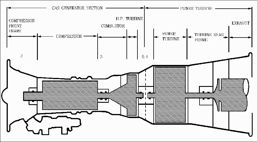
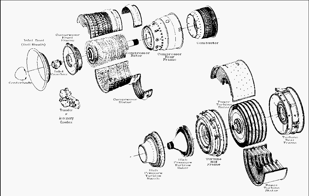
The engines are broken down in two main sections, which themselves are broken down into multiple sections; 1. Gas Generator section and 2. Power Turbine section.
The Gas Generator section contains the:
compressor section, combustor section and the turbine section
The Power Turbine Section contains… well it contains the power turbine. The power turbine is simply a turbine that converts the exhaust gas into mechanical energy. The simplest way to envision this is to think of a windmill. The wind blows on the windmill, which is a turbine, causing the windmill to turn. The power turbine does the exact same thing. The power turbine shaft is what connects the engine to the Main Reduction Gear described a little bit later.
Lube Oil System
Gas turbines use a synthetic oil that is made specifically for the close tolerances, high operating temperatures, and high speeds of the rotating components. This oil is different from the oil that is used in the reduction gear and different from the oil that is used in the controllable pitch propeller (CPP) system. The oil has it’s own oil cooler and reservoir.
Gas turbine engines operate on a “dry sump” lubrication system, meaning that the lube oil is stored in a separate reservoir and is pumped through the engine from that reservoir. The oil circulates through the engine and then collects in the sump in the bottom of the engine, which is sort of like the oil pan on your car’s engine. The oil is collected and then pumped from the sump to the reservoir where it is cooled and filtered. The cooling medium for the turbine oil can be water but can also be lube oil from the reduction gear, which itself is cooled by seawater or through a fresh water cooling loop.


Fuel System
The only point of interest in these engines concerning the fuel system is that the fuel pressure is used to help control airflow through the compressor section.

Note all of the small circular pieces in the picture above. These are guide vanes and they are located in between the rows of compressor blades and help to regulate the flow of air through the engine at varied power settings. Each row of these vanes are connected to linkages of a common hydraulic actuator. This is part of what is known as the Power Level Actuator or PLA. The PLA is operated by a small hydraulic cylinder which uses fuel pressure to extend and retract.
 Animation by Basir Ibrahim at Coroflot.com")
Other than operation of the PLA, there is nothing significant about the fuel oil system in regards to the plant operation.
Starting System
Typically, gas turbine engines are started using air powered starting motors, but they can also be started using electric starters as well. The benefit of using compressed air is that compressed air can be stored and be used without electricity so if there is a total loss of electrical power, the engines can be started very quickly.
Air started turbines use air from two sources to power the air start motor, compressed air from a medium or high pressure air compressor or from another operating turbine. Turbines have the ability to release air from the compressor section, called bleed air, and is often used for starting turbines that are offline and is actually preferred to compressed air start in order to save operational wear on high pressure air compressors. The air starters require a high volume of air, not necessarily high pressure, and an operating turbine engine is able to provide a high volume of air for this operation.
Engine Cooling
These engines are air cooled. The air that is drawn in from the atmosphere is directed through the combustor section after being compressed and the air flows around the outside of the combustors before being mixed with fuel and being turned into high temperature gas . However, not all of the air that is compressed is used for combustion. A significant portion of the air that is compressed is allowed to bypass the combustion section and flow through the turbine section. This air is directed through the turbine blades and shafting and then allowed to flow out into the exhaust gas stream and out the back of the engine.
Bleed Air System
Turbines are typically fitted with a bleed air system. Bleed air is compressed air that ducted, or bled, from the compressor section of the engine. The compressors of a gas turbine engine can supply high volumes of air at a pressure ranging from 59 PSI to upwards of 300 PSI, depending on the power setting of the engine, and that air can be put to productive use.
Previously mentioned is that bleed air often used as a motive force for the starting of off line engines. Another common use is only seen in Naval vessels and that is as part of a system known as a Prairie/Masker System. This system is used on anti-submarine vessels as a way of hiding the propulsion noises from submarines. In theory, it sounds like a rain shower on the surface of the sea. The air for this system comes from gas turbine bleed air and is directed through the propeller shaft and out to blades of the propeller. The blades of the propeller have small holes where that air is allowed to pass. This the Prairie part of the system.

The Masker portion of the system works much the same way except that bleed air is directed to a set of ports along the hull of the ship. This part of the system is used to mask the propulsion machinery noise, making it harder for an enemy submarine to hear the the loudest part of the vessel.
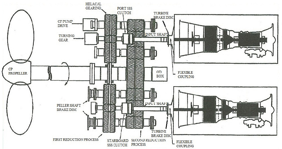
Main Reduction Gear
I thought that the main reduction gear should be included here even though I touched on them in the steam section. The reduction gear used for a gas turbine ship is very similar to those used on steam ships but they still have some differences that are worth mentioning.


The main reduction gear used on gas turbine ships is a double reduction gear box that also houses turbine clutches and brakes and is where some of the components for the controllable pitch propeller are mounted. The function of the main reduction gear is to reduce the speed of the power turbines to something more useable by the propeller shaft. The incoming speed can be as high as 3500 RPM, which is too high for the propeller shaft.
As mentioned above, the gear box is double reduction and utilizes herringbone or double helical gear sets, which means that the speed is reduced in two separate steps. This is done in order to have a smaller gear box, vs one that would make that speed reduction in one step.
Support Systems
Depending on the arrangement of the engineering plant, there can be several support systems needed for the turbines to work.
High Pressure Air System:
As mentioned above, normal starting is accomplished using bleed air from an online turbine. As a back up to the normal start system and for emergency start, high pressure air can be used to start the turbines. High pressure (HP) air, as high as 6000 PSI is stored in air flasks, usually not far from the engines themselves. When needed, the HP air is aligned to the air starter, which is reduced to whatever pressure the starter requires, and then is admitted to the starter when the start process is initiated.
Reduction Gear Lube Oil System:
The reduction gear lube oil system can potentially provide the cooling medium for the turbine oil. Basically, lube oil from the reduction gear is passed through the oil cooler of the LOSCA mentioned above. Reduction gear lube oil removes the heat from the turbine oil, which is then removed by either a central freshwater cooling system or from a seawater cooling system.
Seawater Service System:
The olde school method of cooling machinery was by using a seawater service system and is still widely used through out the world. In this type of system, seawater is drawn in from the sea and passed through piping, strainers, and heat exchangers where the seawater would soak up heat from whatever machine or component is was passing through and in contact with. After the seawater makes it circuit, its is discharged overboard.
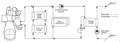
Central Fresh Water Cooling System:
Some vessels have a central fresh water cooling system. In this arrangement, multiple pieces of equipment are cooled using freshwater circulating through oil coolers. After making the freshwater cooling circuit, the freshwater is cooled by seawater through a seawater circulation system or through components known as keel coolers or box coolers. At this point, the water is circulated through the system again. This known as a closed loop system where as the seawater service system is an open loop system.
The benefit to a system like this is that the risk of salt contamination to equipment is greatly reduced as is the maintenance required for the piping and system components. Even though they can be complex systems, central freshwater cooling systems will be cheaper to install and maintain since the components aren’t exposed to corrosive nature is seawater.
Engine Room Ventilation System:
This is a simple one… ventilation air is ducted to the engine modules in order to internally cool the module.
Ship’s Service Steam System:
Depending on the area that the vessel is operating and what kind of fuel the engines will be using, steam is sometimes used as source of heating the fuel in order to reduce the viscosity of the fuel and make it easier to pump and burn.
Ship’s Potable Water System:
As I mentioned before, these engines need to be clean on the inside. Because of the high volume of air that is drawn into these engines, dirt, salt, and whatever else will accumulate on the compressor blades so as a preventative maintenance measure, fresh water and soap can be sprayed into the turbine while the turbine is “motored”, which simply means that the engine is turned over using the air starter.
Two Most Common Plant Configurations
COGAG configuration
COmbined Gas turbine And Gas Turbine.
Two gas turbines connected to a common propeller shaft. In this configuration, both engines can be of the same power rating or one engine can be a higher horsepower rating than the other and then the higher powered engine becomes known as a “boost turbine”.
The US navy uses this configuration with both engines being of the same power rating.
CODAG configuration
Combined Diesel And Gas Turbine
In this configuration, one or two diesel engines are connected to a gas turbine. This arrangement offers some incredible flexibility in how the plant is configured and operated but requires some pretty interesting engineering in order to make all of this work together.
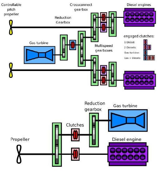

The benefit to this configuration is that the diesel engines can be used at speeds where they are most efficient and the turbine can be used at speeds where it is most efficient and all three engines can be combined together when the vessel needs to get somewhere with a quickness. I’ve seen this configuration on the US Coast Guard’s first National Security Cutter when the vessel was being built and it took a while for me to realize what I was looking at since I had never seen anything like this before. This is a very complicated system and the design guys managed to fit it all into a very confined space.
There are other configurations where steam turbines and electric propulsion motors are thrown into the mix with gas turbines and diesel engines, but the two above configurations are the most common and the other configurations add steam turbines and electric propulsion motors into the mix. The configurations are really just limited to the imagination of the ship designers.
Conclusion
So… this one has taken a lot longer for me to write than I had intended. The conclusion kinda sucks but I’m kinda over this part and ready to put it behind me and move on to whatever the next thing is. If there is any interest in continuing this series then I’d like to hear from yall. Let me know if this is still interesting or if I need to move on to something else.
I hope that it wasn’t too technical and dry. Let me know what you think in the comments section. If you like what I write, please subscribe and share. As always, I hope that you have a blessed day.
Fair winds and following seas,
Nate